Hello and welcome back. Today, let’s learn about Cisco’s Unified Computing Systems (UCS) technology. If you haven’t heard of Cisco UCS before, this might be a good opportunity for you to keep yourself updated with the recent developments in IT industry. Basically, UCS is an aggregation of computing systems, virtualization, switching fabric and centralized management for deploying and running the entire data center. As part of UCS, Cisco provides rack-mount servers and blade servers for computing and Nexus/MDS switches for fabric switching. Similarly, Cisco has also created Cisco UCS Manager, using which the whole data-center/fabric domain can be managed centrally.
About Cisco UCS
Cisco UCS is such a vast subject that covering it whole in a single blog post will be simply impossible and unjust. However, I hope to learn it further myself and share my findings in my upcoming blog series. So, for now, let’s just get into the topic on hand i.e. Cisco UCS Mini. To briefly introduce UCS Mini, it is an all-in-one computing, networking and management solution designed mainly for small offices or remote branches. It comes with all the benefits of UCS technology in an affordable cost and smaller size, which is ideal for small deployment scenarios. The figure below is the front view of a Cisco UCS Mini.
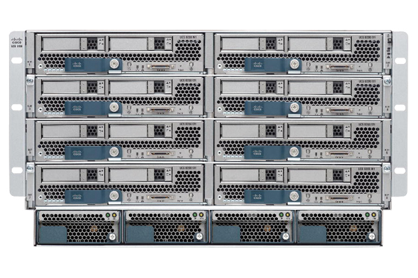
Well, if you are already familiar with UCS, understanding UCS Mini won’t be an issue for you because it is just a condensed form of typical UCS. The blade servers, power modules, fan modules, and UCS Manager are similar to that of UCS. The primary difference between UCS and UCS Mini is the way Fabric Interconnects (FI) are used. In usual UCS, separate Nexus switches, mainly Nexus 5000 or 7000 series are used as FI for fabric switching and blade chassis contains the IO modules that connect to the FI. Since high end Nexus switches with high port density are used as FI in UCS, it can scale to hundreds of servers in a data-center. Whereas UCS Mini comes with two FIs (FI-6324) that are already embedded and integrated with IO modules of Blade chassis (5108). Each of these Fabric Interconnects contains four 10 Gigabit unified ports and one 40 Gigabit unified port. And this configuration allows UCS Mini to scale upto 15 servers containing 8 UCS blade servers and 7 UCS rack-mount servers. Here’s the rear view of UCS Mini:
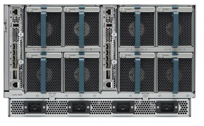
Beginning from the top left, we’ve got a FI placed vertically, then four fan modules, another FI and again four fan modules. Note that all of these components along with blade servers and power modules in the front are modular and hot swappable. Then we’ve four power sockets on the bottom of the chassis. Here’s the closeup look of the FI 6324.

Getting Started
Now that I’ve briefly introduced you to UCS Mini, let’s get started with the configuration section. First, we need to mount this blade chassis to the rack and then insert all the modules if not already inserted. Note that blade chassis tends to be very heavy, so I think it’ll make sense to take out all the blades and modules out while mounting it and then reinsert them after rack mount. After that, we can connect the power cables to the chassis and power it on. As expected from heavy equipment, this system also draws huge power and makes initial loud noise.
To begin the configuration part, we first need to connect console (port on the bottom) to one of the Fabric Interconnects and after we’re done with it, we can switch the console to another FI. When console is accessed, the FI asks us to configure the management IP address and login credentials for it. Once done, we can connect its management interface (port on top) to our laptop or switch and access the Cisco UCS Manager by browsing its IP address in the web browser. Note that Java 1.6 or later is required for it to run smoothly. Here’s the screenshot of the homepage:

Since we’re configuring this device for first time, let’s choose Express Setup button, which will take us through a setup wizard. Then select Initial Setup.

In the next screen, it asks us to choose whether this is a standalone setup or cluster setup. Since we’ve two FIs, we can go for Cluster mode. But it totally depends on our requirements. In my case, I initially did a standalone setup and then changed it to cluster mode, just for the sake of learning. When setting cluster mode, we need to provide a separate virtual IP address along with management IP of FI. This virtual IP will represent the cluster i.e. if a primary FI fails, the control plane will move to secondary FI.

After I configured both of the FIs and connected a 10 Gigabit link to each of them, my topology looks like this:

The ports on FIs which are colored green are the active ports. I’ve configured these ports as Uplink ports. Remember that until we configure these ports on FIs, these will remain in disabled or down state. There are different types of ports available in Cisco UCS, which ought to be used in different scenarios. So, we need to be sure of which type we need to choose. In my case, I needed to connect my Blade system to my network switch, so I configured these ports as Uplink Ports. If we need to connect it to storage device, we need to set it to type Appliance Port. Similarly, if we need to associate a UCS rack server to our Blade system, we need to configure this port as Server Port. Other port types are used in the similar fashion.
Configuring Blade Servers
Blade servers in UCS architecture are merely the computing modules that are powered, managed and operated by the UCS system. So if we perceive these servers as the traditional servers, we’re very likely to have trouble getting them running. If you’re wondering why, the answer is simple: Blade servers aren’t meant to be handled as traditional servers, rather they’re the component of a unified architecture and thus, are supposed to work in coordination with other components.
If so, then one might question how are these servers configured and operated. The answer to this question is again quite simple and involves only two words: Service Profiles. Well, these service profiles are the set of rules or attributes which define how the servers should be profiled and operated. Once defined and associated to a server, a service profile takes complete control of that server. This provides agility to the system. Since a service profile determines how the server runs, we can change the behavior of a server on the fly by re-associating it with another profile. We can also define a standard Service Profile, create its clones and associate each to the server so that all servers run with same attributes.
First, let’s start off by assigning management IP addresses to our blade servers so that we can access their individual CIMC and KVM. For that purpose, we need to create a pool of management IP addresses and the system will automatically assign these IPs to the servers.

Now at minimum, we need to define a pool of MAC addresses of virtual Network Interface Cards (vNICs), which will be assigned to the blade servers. These vNICs will act as the real NICs inside the servers and we can add multiple vNICs to the servers without having to add new physical NIC to the chassis.

If we’re using Fibre Channel (FC) for SAN connectivity, we also need to create a pool of WWNs for our virtual Host Bus Adapters (vHBAs). Then, there is one other thing that we must have and that is a LAN Connectivity Policy. This defines how the vNICs are added to the servers and how the servers connect to the LAN. Without this policy, the servers won’t be able to communicate with other blades or the external network. Here, we define the VLANs that need to be passed to the servers.

Then, we can go ahead and create the required Service Profiles for our servers. For adding a service profile, Cisco UCS Manager provides a step-by-step wizard. We set the pools and LAN connectivity policy that we created above to this service profile. If there’s something wrong with our service profile, it warns us at the time of submission. If a service profile is created correctly, we can simply associate it with a server. For multiple servers, we can clone this service profile and associate each of them to chosen servers. Upon successful association with service profile only, a server can started and booted.
Well, I think this is it. After the server is booted, we can take it further the same way as we do other Cisco servers or any other servers for that matter. We can boot the servers from SAN (if necessary settings have been done in the service profile) or from the local disks by configuring logical volume or RAID volume. Further, we can simply install the operating system or hypervisor of our choice and get our servers running. Remember that Cisco UCS also integrates seamlessly with the popular virtual platforms like VMware and Microsoft HyperV. On using these virtual platforms, the virtual machines can also be managed on the UCS level.
I think this post has already been too long. I hope to cover this topic in further depth in my future blog posts. Up to now, I hope you’ve learned something new and/or useful. Please let me know of your feedback or suggestion in the Comments section below. Thank you for reading!
Leave a Reply