Welcome back! In this post, I’m getting into somehow different topic than my usual ones. Here, the subject matter that I’m diving into is storage traffic switching with Cisco MDS series switches. If you’re new to this subject, here are some basic introductions: First, Storage Area Network (SAN) is much like the well-known Local Area Network (LAN), with an exception that it carries storage traffic or SCSI commands among storage devices (target) and servers/clients (initiator). There are mainly two technologies that are used for SAN: Fibre Channel (FC) which utilizes fibre channel protocol and iSCSI which utilizes IP.
Lab Overview
Devices
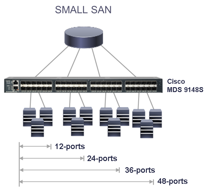
In this lab, I’ve got two Cisco MDS 9148S switches, two Cisco UCS C240-M4 servers and two Storage appliances. With these devices in hand, I intend to setup a SAN topology using Fibre Channel. Although Cisco MDS 9148 series switches have 48 fibre channel ports, only the first 12 of them can acquire port license by default and the remaining ports have to be activated by purchasing additional licenses from Cisco. So, all of my cabling and configuration will be done on these first 12 ports of each switch.
Transceivers and Cabling
For cabling, I’m going to use SR-type SFP transceivers on all of my devices and multi-mode fiber cables for inter-device connectivity. I then connect all of my storage devices and servers to the Cisco MDS switches as follows:
Switch 1:
FC 1/1: Server 1 -> HBA 1 -> Port 1
FC 1/2: Server 2 -> HBA 1 -> Port 1
FC 1/3 : Storage 2 -> Controller A -> Channel 5
FC 1/4: Storage 2 -> Controller B -> Channel 5
FC 1/5: Storage 1 -> Controller A -> Channel 5
FC 1/6: Storage 1 -> Controller B -> Channel 5
FC 1/11-12: Switch 2 (ISL trunks)
Switch 2:
FC 1/1: Server 1 -> HBA 1 -> Port 0
FC 1/2: Server 2 -> HBA 1 -> Port 0
FC 1/3 : Storage 2 -> Controller A -> Channel 4
FC 1/4: Storage 2 -> Controller B -> Channel 4
FC 1/5: Storage 1 -> Controller A -> Channel 4
FC 1/6: Storage 1 -> Controller B -> Channel 4
FC 1/11-12: Switch 1 (ISL trunks)
Cisco MDS Configuration
Initial Setup
When we’re trying to configure a newly purchased Cisco MDS switch, we can simply utilize the setup utility provided by Cisco. To do so, we need to connect the device’s console to our laptop or PC and power on the device. Once the switch boots up, it prompts for the admin password and asks if we’d like to run the setup wizard, to which I answer Yes. Then, it asks for some more options, for which we can basically choose default values. You can refer to this Cisco documentation to learn about it.
Switch 1 Config
After the cabling is completed and the initial configuration is done, let’s begin the further configuration by setting up the description in every connected switch ports and creating a port channel for aggregation of links fc1/11 and fc1/12.
[code]
LAB-MDS-1# conf t
LAB-MDS-1(config)# int fc1/1-12
LAB-MDS-1(config-int)# port-license acquire
LAB-MDS-1(config-int)# no shutdown
LAB-MDS-1(config-int)# int fc1/1
LAB-MDS-1(config-int)# switchport description ***UCS-2-Port-1***
LAB-MDS-1(config-int)# int fc1/2
LAB-MDS-1(config-int)# switchport description ***UCS-1-Port-1***
LAB-MDS-1(config-int)# int fc1/3
LAB-MDS-1(config-int)# switchport description ***Storage-2-Ctr-A-Channel-5***
LAB-MDS-1(config-int)# int fc1/4
LAB-MDS-1(config-int)# switchport description ***Storage-2-Ctr-B-Channel-5***
LAB-MDS-1(config-int)# int fc1/5
LAB-MDS-1(config-int)# switchport description ***Storage-1-Ctr-A-Channel-5***
LAB-MDS-1(config-int)# int fc1/6
LAB-MDS-1(config-int)# switchport description ***Storage-1-Ctr-B-Channel-5***
LAB-MDS-1(config-int)# int fc1/11
LAB-MDS-1(config-int)# switchport description ***ISL-Trunk-1***
LAB-MDS-1(config-int)# channel-group 1
LAB-MDS-1(config-int)# int fc1/12
LAB-MDS-1(config-int)# switchport description ***ISL-Trunk-2***
LAB-MDS-1(config-int)# channel-group 1
[/code]
Let’s also create the port-channel that we’ve called on the interfaces fc1/11 and fc1/12.
[code]
interface vsan100
no shutdown
interface port-channel1
channel mode active
switchport description ***Port-Channel-ISL-Trunk***
switchport rate-mode dedicated
[/code]
Then, let’s create the virtual SAN (VSAN) and associate the interfaces to this VSAN.
[code]
LAB-MDS-1(config)# vsan database
LAB-MDS-1(config-vsan-database)# vsan 1 suspend
LAB-MDS-1(config-vsan-database)# vsan 100 name "My-VSAN"
LAB-MDS-1(config-vsan-database)# vsan 100 interface port-channel1
LAB-MDS-1(config-vsan-database)# vsan 100 interface fc1/1-10
LAB-MDS-1(config)# system default zone default-zone permit
LAB-MDS-1(config)# system default zone distribute full
LAB-MDS-1(config)# zone mode enhanced vsan 100
[/code]
Here I’ve created a VSAN with id 100 and included all of my available interfaces into it. Simultaneously, I also suspended vsan 1, so that it won’t remain being the native vsan.
Now, comes probably the most important task in SAN setup i.e. Zoning. Zoning allows us to control the traffic flowing between the devices, similar to the Access Control Lists in IP network. There are mainly two ways to setup zones in Cisco MDS: interface based zoning and WWN based zoning. When interface based zoning is done, only the member interfaces can communicate with each other. So, if the devices are connected on different ports of switch, the zoning might not work correctly. Whereas with WWN based zones, devices can only communicate with other devices with member PWWNs. Thus, it works correctly even when ports are changed, but doesn’t work if the ports or HBA cards on server or storage are changed. Here, I’m using PWWN based zoning. If you choose to use interface based zoning, that’s simply fine.
In this case, I’m also creating fcaliases for each PWWNs of devices so that I can identify and manage them easily. I’m then going to associate these fcaliases in the zone configuration.
[code]
fcalias name UCS-1-Port-0 vsan 100
member pwwn 10:00:00:90:fa:de:f5:9a
fcalias name UCS-1-Port-1 vsan 100
member pwwn 10:00:00:90:fa:de:f5:9b
fcalias name Storage-1-Ctr-A-Channel-5 vsan 100
member pwwn 22:00:00:d0:23:05:43:2a
fcalias name Storage-1-Ctr-B-Channel-5 vsan 100
member pwwn 22:00:00:d0:23:15:43:2a
fcalias name Storage-1-Ctr-A-Channel-4 vsan 100
member pwwn 21:00:00:d0:23:05:43:2a
fcalias name Storage-1-Ctr-B-Channel-4 vsan 100
member pwwn 21:00:00:d0:23:15:43:2a
fcalias name Storage-2-Ctr-A-Channel-4 vsan 100
member pwwn 21:00:00:d0:23:05:6b:6f
fcalias name Storage-2-Ctr-A-Channel-5 vsan 100
member pwwn 22:00:00:d0:23:05:6b:6f
fcalias name Storage-2-Ctr-B-Channel-5 vsan 100
member pwwn 22:00:00:d0:23:15:6b:6f
fcalias name Storage-2-Ctr-B-Channel-4 vsan 100
member pwwn 21:00:00:d0:23:15:6b:6f
fcalias name UCS-2-Port-1 vsan 100
member pwwn 10:00:00:90:fa:81:56:4d
fcalias name UCS-2-Port-0 vsan 100
member pwwn 10:00:00:90:fa:81:56:4c
fcalias name My-VSAN vsan 100
[/code]
Now, I need to create zones to allow communication between each server and storage. That way, these devices will have their own separate communication path, which won’t be accessible to outsider devices.
[code]
zone name UCS1-SAN1 vsan 100
member fcalias UCS-1-Port-0
member fcalias UCS-1-Port-1
member fcalias Storage-1-Ctr-A-Channel-5
member fcalias Storage-1-Ctr-B-Channel-5
member fcalias Storage-1-Ctr-A-Channel-4
member fcalias Storage-1-Ctr-B-Channel-4
zone name UCS1-SAN2 vsan 100
member fcalias UCS-1-Port-0
member fcalias UCS-1-Port-1
member fcalias Storage-2-Ctr-A-Channel-4
member fcalias Storage-2-Ctr-A-Channel-5
member fcalias Storage-2-Ctr-B-Channel-5
member fcalias Storage-2-Ctr-B-Channel-4
zone name UCS2-SAN1 vsan 100
member fcalias Storage-1-Ctr-A-Channel-5
member fcalias Storage-1-Ctr-B-Channel-5
member fcalias Storage-1-Ctr-A-Channel-4
member fcalias Storage-1-Ctr-B-Channel-4
member fcalias UCS-2-Port-1
member fcalias UCS-2-Port-0
zone name UCS2-SAN2 vsan 100
member fcalias Storage-2-Ctr-A-Channel-4
member fcalias Storage-2-Ctr-A-Channel-5
member fcalias Storage-2-Ctr-B-Channel-5
member fcalias Storage-2-Ctr-B-Channel-4
member fcalias UCS-2-Port-1
member fcalias UCS-2-Port-0
[/code]
At last, I need to create a zoneset belonging to the vsan 100 and containing the zones created above. And every time I make changes to the zones and commit the zoneset, the zones are synchronized in both of the switches via ISL link.
[code]
zoneset name Zoneset_1-V100 vsan 100
member UCS1-SAN1
member UCS1-SAN2
member UCS2-SAN1
member UCS2-SAN2
zone commit vsan 100
zoneset activate name Zoneset_1-V100 vsan 100
[/code]
Switch 2 Config
[code]
conf t
int fc1/1-12
port-license acquire
no shutdown
int fc1/1
switchport description ***UCS-2-Port-0***
int fc1/2
switchport description ***UCS-1-Port-0***
int fc1/3
switchport description ***Storage-2-Ctr-A-Channel-4***
int fc1/4
switchport description ***Storage-2-Ctr-B-Channel-4***
int fc1/5
switchport description ***Storage-1-Ctr-A-Channel-4***
int fc1/6
switchport description ***Storage-1-Ctr-B-Channel-4***
int fc1/11
switchport description ***ISL-Trunk-1***
channel-group 1
int fc1/12
switchport description ***ISL-Trunk-2***
channel-group 1
interface vsan100
no shutdown
interface port-channel1
channel mode active
switchport description ***Port-Channel-ISL-Trunk***
switchport rate-mode dedicated
system default zone default-zone permit
system default zone distribute full
zone mode enhanced vsan 100
[/code]
Since all of the fcalias, zones and zoneset information are synchronized to this switch from switch-1, we don’t need to do much setup on this switch.
Well, this is it! I hope you’ve learned something from this article. Please let me know of your suggestion and feedback in the Comments section below. See you later. Thank you!
Leave a Reply